From the Lean Six Sigma Briefcase
Engineering Case Study
Product Upgrade Pre-Launch Out-of-Box Failure (OOBF)
Root Cause Analysis: The Power of 'Why 5 Times'
About 3 weeks before launch of a major system upgrade on a product called ‘Saluki’ with 4 years in the market, a show-stopper problem was discovered in the pre-launch stock of finished ‘Saluki-II’ product. The upgrade involved mechanical, electronic, and software changes to improve field performance and reliability.
We had successfully completed design verification and validation, and were nearly ready for market launch. But when samples of ‘Saluki-II’ product were pulled from stock to retest before shipping (‘Out-of-Box’ testing), 2 units out of 30 pulled were found to have their event and error log (EEL) memory lost after being in finished goods inventory (FGI) for 45-60 days.
Thirty more samples were pulled and 3 of them had the same failure. The Operations director initiated a full purge of FGI and found 20 out of 500 had the problem (4%).
Based on the symptoms exhibited by the failing units, the consensus among the business division’s senior executives responsible for the product launch was that the root cause must be either a batch of defective lithium batteries (non-rechargeable primary cells), or defective event and error log memory chips. The Supply Chain manager contacted the suppliers of both components to get their urgent support. The Ops director immediately set up a project team to perform a thorough investigation including root cause analysis, and to implement corrective actions to resolve the failures.
The project team consisted of manufacturing engineers from System Assembly and PCBA Assembly, production technicians, R&D electronic and software engineers, quality engineers, and supply chain specialists, 12 members in total. The varying expertise and perspectives were selected deliberately; having a variety of backgrounds for a problem-solving team is often helpful so that “tunnel vision” does not prevent the team from overlooking a possible cause. Because of the urgent nature of the situation, the project was top priority for the 12 team members until the problem could be resolved.
I was the PCBA engineering manager at the time and was assigned to lead the root cause analysis investigation. It took us about 3 weeks to identify and confirm the root cause of the problem, then another 2 weeks to define the corrective and preventive actions (CA/PA). We met every afternoon for 45-60 minutes to review new findings, analyze new data, and decide on actions to complete before the next day’s meeting. We made use of many Lean Six Sigma tools; about half of the project team had some training in Lean Six Sigma, and shared their knowledge with the others as the work progressed.
The most impactful tools we employed in the root cause analysis were:
- Is – Is Not: Identify where the failure did or did not happen, giving clues to possible causes.
- Failure Modes, Effects, and Criticality Analysis (FMECA): Both Design and Process FMECAs were reviewed to identify possible defects that could lead to the failure.
- Process Flow diagrams, expanded into a Value Stream Map (VSM): Prior to finding the memory failures, the process flows for PCBA and Final Assembly had been treated separately. One early project team action was to integrate the separate flows and include any “offline” steps such as wire harness assembly and code download, to make a complete VSM. Even some supplier operations were incorporated, in order to have a complete picture of the process or ‘value stream’ within which the failures were occurring.
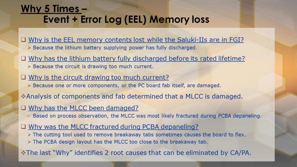
- Why 5 Times, or 5-Why Analysis: Ask the question “Why?” concerning the occurrence of a failure or defect or anomaly, and carefully answer the question. Then ask “Why?” for the first answer, and reiterate until the answer is believed to be the root cause.
The 5-Why Analysis turned out to be the technique that revealed the root cause for the ‘Saluki-II’ memory loss problem, although all of the other work prior to 5-Why certainly provided knowledge and context, and contributed to the solution.
The memory chip containing the ‘Saluki-II’ event and error log (EEL) was located on a PCBA, along with a lithium battery to keep it powered always (rated for minimum 10-year life, based on the current drawn by the circuit design). A control chip (32-pin SOIC) and a few surface mount resistors and capacitors were also in the EEL circuit.
The EEL circuit design was similar but not identical to ‘Saluki,’ making use of a new low-power control chip, and the circuit board layout was completely redesigned.
In analyzing defective product, the technicians would remove the dead lithium battery from the PCBA and replace it with a new one, then test whether the new battery would discharge as rapidly. If it did, the next step was to remove components that might be causing the battery to discharge. In doing so, they noted several times that one of the surface mount capacitors would break when they unsoldered it from the board. In spite of their effort to be careful, it continued to happen.
After the 4th or 5th occurrence, we did a 5-Why on this observation, and suggested maybe the capacitor was already broken before it was unsoldered, rather than breaking as a result of unsoldering. A little offline research indicated that for the type of capacitor used (called ‘MLCC’ or multi-layer chip capacitor), fracture can occur during handling, for example flexing of the PCBA, causing the part to short-circuit. In the memory circuit, the additional current due to the damaged capacitor would cause the lithium battery lifetime to drop from 10 years to a few days or weeks, depending on severity of the fracture.
A failure analysis lab used SEM imaging and other techniques to confirm fracture of the capacitor on 2 defective PCBAs, and no fracture on a “good” PCBA we provided for reference.
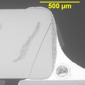
SEM photograph of an MLCC fracture similar to that seen in the Saluki-II failure. The diagonal crack can be seen in the cross section.
We were not quite finished, though. Once we knew a damaged MLCC was causing the memory loss, we then needed to continue our root cause analysis to find the reason(s) for the fractured capacitor. The expanded process flow diagrams helped provide that answer, along with another round of 5-Why.
The PCBAs were fabricated and assembled in panels of 3 boards, common production practice for small circuit boards. The part was very close to a ‘breakaway tab’ on the edge of the PCBA and could be damaged when the PCBAs were separated after completing assembly and test.
The Corrective Action (CA) therefore was to improve the method for separating the 3 PCBAs in the panel by use of a router rather than the hand-held cutting tool that had been used, resulting in a greatly reduced likelihood of failure.
Further, a Preventive Action (PA) involving re-layout of the circuit board to place the capacitor away from the breakaway tab, eliminated the failure root cause completely after the new design was cut in to production.
Recall that the consensus opinion when the failures were first observed was that either defective batteries or memory chips were the cause of the EEL memory loss. Both component suppliers were brought into the analysis through the Supply Chain manager. Samples of batteries and chips from defective Saluki II units were provided to them for analysis, along with purchase order history and part date codes to narrow down the suppliers’ analysis scope.
However, despite the significant pressure applied on the suppliers by our Operations, Quality, and Supply Chain executives, those components were not found to have any intrinsic failures. And indeed, all of the analytical results of my team’s work pointed us away from both the battery and the memory chip as root causes.
Had we relied only on the battery and memory suppliers to “solve our problem,” we would have encountered a 3- to 6-week delay getting started on determining the actual root cause.
Therein lies an important lesson for root cause analysis:
Don’t let your first reaction cloud the analysis. Follow the data where it takes you and be willing to accept that the initially assumed answer may be based on incomplete information or erroneous assumptions, and may therefore be the wrong answer.
A final note. Most explanations about the 5-Why process make it seem as if it is a fairly simple procedure that takes 3 or 4 people a few minutes or an hour to complete. In reality, often the first one or two “Why” responses come rather quickly, but the subsequent ones take more time, because they require deeper analysis than a few people can do in a conference room setting or video chat. You may need to go to the ‘gemba’ and make some further observations, interview a few people who are not in the 5-Why team, gather “forensic evidence,” or do an experiment.
In the case of the ‘Saluki-II’ lithium battery / capacitor problem, we spent the better part of 3 one-hour meetings on our 5-Why analyses, with 3 or 4 offline sessions in the labs and production lines observing technicians and asking them detailed questions so we could understand exactly what was happening, and thereby feel certain we had arrived at the actual root cause of the failures.
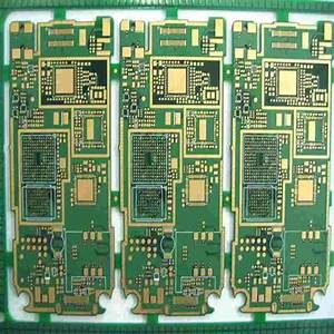
Panel of 3 PCBAs similar to the Saluki-II panel. The breakaway tabs between individual boards can be seen in the photo.
Feel free to contact me to discuss 5-Why or the other tools described in this report, and how to bring the benefits of Lean Six Sigma to your current project.
~ Dann